A mapping mode defines how Windows converts logical coordinates used by an application into device coordinates used for drawing within a device context (DC). Logical coordinates represent the positions specified by the application, while device coordinates represent the corresponding pixel positions on the display or output device.
The selected mapping mode determines:
- the units used for logical coordinates;
- the scaling between logical units and device units;
- the position of the coordinate origin; and
- the orientation and direction of the X-axis and Y-axis.
In the default mapping mode (MM_TEXT), one logical unit corresponds to one pixel. The coordinate origin is located at the upper-left corner of the client area, the X-axis increases to the right, and the Y-axis increases downward.
Windows provides several predefined mapping modes, allowing applications to work in units such as pixels, inches, millimetres, or arbitrary user-defined units. The available mapping modes are listed below.
| Mapping Mode | Logical Unit | x-axis and y-axis |
| MM_TEXT | Pixel | Positive x is to the right; positive y is down |
| MM_LOMETRIC | 0.1 mm | Positive x is to the right; positive y is up. |
| MM_HIMETRIC | 0.01 mm | Positive x is to the right; positive y is up. |
| MM_LOENGLISH | 0.01 in | Positive x is to the right; positive y is up. |
| MM_HIENGLISH | 0.001 in | Positive x is to the right; positive y is up. |
| MM_TWIPS | 1/1440 in | Positive x is to the right; positive y is up. |
| MM_ISOTROPIC | user-specified | user-specified |
| MM_ANISOTROPIC | user-specified | user-specified |
To select a different mapping mode, use the function SetMapMode()
int SetMapMode(HDC hdc,int iMode);
where
hdc – A handle to the device context.
iMode – The new mapping mode.
If the function succeeds, the return value is the previous mapping mode. If the function fails, the return value is zero.
Programmable Mapping Modes
The MM_ISOTROPIC and MM_ANISOTROPIC mapping modes differ from the predefined mapping modes in that the relationship between logical units and device units is defined by the application rather than by Windows.
The two mapping modes differ in how scaling is applied. With MM_ISOTROPIC, the horizontal and vertical scaling factors are always kept equal, ensuring that one logical unit represents the same distance in both directions. This preserves the aspect ratio of graphics, preventing circles from becoming ellipses.
With MM_ANISOTROPIC, the horizontal and vertical scaling factors are independent. This allows the application to scale the X-axis and Y-axis by different amounts, making it possible to stretch or compress graphics horizontally or vertically.
When either of these mapping modes is selected, the application must define the logical coordinate system by specifying the window extents and viewport extents. The logical extents of the coordinate system are established by calling SetWindowExtEx(), while the corresponding size of the viewport in device units is specified by calling SetViewportExtEx(). Windows then uses these values to convert logical coordinates into device coordinates.
SetWindowExtEx
Sets the horizontal and vertical extents of the window for a device context by using the specified values.
BOOL SetWindowExtEx( HDC hdc, int x, int y, LPSIZE lpsz );
hdc – A handle to the device context.
x – The window’s horizontal extent in logical units.
y – The window’s vertical extent in logical units.
lpsz – A pointer to a SIZE structure that receives the previous window extents, in logical units. If lpSize is NULL, this parameter is not used.
If the function succeeds, the return value is nonzero. Otherwise, the return value is zero.
SetViewportExtEx
Sets the horizontal and vertical extents of the viewport for a device context by using the specified values.
BOOL SetViewportExtEx( HDC hdc, int x, int y,LPSIZE lpsz);
hdc – A handle to the device context.
x – The horizontal extent, in device units, of the viewport.
y – The vertical extent, in device units, of the viewport.
lpsz – A pointer to a SIZE structure that receives the previous viewport extents, in device units. If lpSize is NULL, this parameter is not used.
If the function succeeds, the return value is nonzero. If the function fails the return value is zero.
Moving the Origin
By default, the origin of a device context, regardless of the mapping mode, is located in the upper-left corner of the display. This origin can be changed using the API functions SetWindowOrgEx and SetViewportOrgEx.
The former changes the window origin, while the latter changes the viewport origin. The prototypes for these functions are as follows:
BOOL SetWindowOrgEx(HDC hdc,int x,int y,LPPOINT lppt); BOOL SetViewportOrgEx( HDC hdc, int x, int y, LPPOINT lppt);
hdc – A handle to the device context.
x – The x-coordinate of the new viewport origin.
y – The y-coordinate of the new viewport origin.
lppt – A pointer to a POINT structure that receives the previous viewport origin, in device coordinates. If lpPoint is NULL, this parameter is not used.
If the function succeeds, the return value is nonzero. If the function fails, the return value is zero.
Example
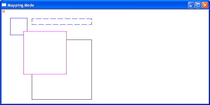
The following short program draws 5 squares under different mappings to illustrate the different display characteristics of each Mapping Mode in Windows.