The mapping mode determines how Windows converts logical coordinates used by an application into device coordinates (pixel positions) on the output device. Logical coordinates represent the values specified by the program when drawing graphics or text, while device coordinates correspond to the actual pixel locations on the screen or printer.
The selected mapping mode defines:
- How logical units are converted into device units (pixels or physical units).
- The position of the coordinate system origin.
- The orientation of the X-axis and Y-axis.
- Whether the coordinate values increase or decrease relative to the origin.
By default, a Windows device context uses the MM_TEXT mapping mode. In this mode:
- One logical unit is equal to one pixel.
- The origin
(0,0)is located at the upper-left corner of the client area. - The X-axis increases to the right.
- The Y-axis increases downwards.
Windows provides eight predefined mapping modes, each suited to different drawing requirements. These are listed below
| Mapping Mode | Logical Unit | x-axis and y-axis |
| MM_TEXT | Pixel | Positive x is to the right; positive y is down |
| MM_LOMETRIC | 0.1 mm | Positive x is to the right; positive y is up. |
| MM_HIMETRIC | 0.01 mm | Positive x is to the right; positive y is up. |
| MM_LOENGLISH | 0.01 in | Positive x is to the right; positive y is up. |
| MM_HIENGLISH | 0.001 in | Positive x is to the right; positive y is up. |
| MM_TWIPS | 1/1440 in | Positive x is to the right; positive y is up. |
| MM_ISOTROPIC | user-specified | user-specified |
| MM_ANISOTROPIC | user-specified | user-specified |
To select a different mapping mode, use the CDC member function SetMapMode() –
virtual int SetMapMode( int nMapMode );
where
nMapMode specifies the new mapping mode. The Return Value is the previous mapping mode.
Programmable Mapping Modes
Unlike the predefined mapping modes, MM_ISOTROPIC and MM_ANISOTROPIC allow the programmer to define how logical coordinates are mapped to device coordinates. Instead of using fixed measurement units such as pixels or millimetres, the application specifies the relationship between the logical drawing area (the window) and the physical drawing area (the viewport).
The two programmable mapping modes differ as follows:
MM_ISOTROPICmaintains the same scale factor for both the X-axis and Y-axis. This preserves the aspect ratio of graphics, ensuring that circles remain circular and shapes are not distorted.MM_ANISOTROPICallows different scale factors for the X-axis and Y-axis. This permits graphics to be stretched or compressed independently in each direction.
When either of these mapping modes is selected, the application must define the logical size of the drawing area (the window extent) and the corresponding device size (the viewport extent).
The logical extents are specified using the SetWindowExt() member function, while the device extents are specified using SetViewportExt().
The prototypes are:
SetWindowExt
Sets the x- and y-extents of the window associated with the device context.
virtual CSize SetWindowExt( int cx, int cy );
virtual CSize SetWindowExt( SIZE size );
Parameters
cx – Specifies the Window x-extent (in logical units).
cy – Specifies the Window y-extent (in logical units).
size – Specifies the Windows x- and y-extents (in logical units).
Returns the previous extents of the window as a CSize object. If an error occurs, the x- and y-coordinates of the returned CSize object are set to 0.
SetViewportExt
Sets the x- and y-extents of the device context’s viewport.
virtual CSize SetViewportExt( int cx, int cy );
virtual CSize SetViewportExt( SIZE size );
Parameters
cx – Specifies the x-extent of the viewport (in device units).
cy – Specifies the y-extent of the viewport (in device units).
size – Specifies the x- and y-extents of the viewport (in device units).
Returns the previous extent of the viewport as a CSize object. When an error occurs, the x- and y-coordinates of the returned CSize object are set to 0.
For example, if SetViewportExt is called with parameters 100,50 and SetWindowExt is called with parameters 100,100 this will mean that each logical unit in the X direction will equate to 1 device unit and each logical unit in the y direction will equate to 1/2 a unit in the device coordinate.
Moving the Origin
By default, the origin of a device context is located at the upper-left corner of the client area, regardless of the mapping mode being used. The origin represents the point (0,0) from which all logical coordinates are measured.
Windows allows the origin to be repositioned using the CDC member functions SetWindowOrg() and SetViewportOrg().
SetWindowOrg()changes the logical origin (window origin) of the coordinate system.SetViewportOrg()changes the device origin (viewport origin), effectively moving where the logical origin appears on the output device.
The prototypes for these functions are:
CPoint SetWindowOrg( int x, int y );
CPoint SetWindowOrg( POINT point );
And
virtual CPoint SetViewportOrg( int x, int y );
virtual CPoint SetViewportOrg( POINT point );
where
cx – Specifies the x-extent (in logical units) of the window.
cy – Specifies the y-extent (in logical units) of the window.
size – Specifies the x- and y-extents (in logical units) of the window.
Returns the previous origin or viewport of the window as a CPoint object
Example
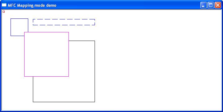
The following short program draws 5 squares under different mapping to illustrate the different display characteristics of each